Reverse Engineering a Car’s Factory Display for Custom Gauges
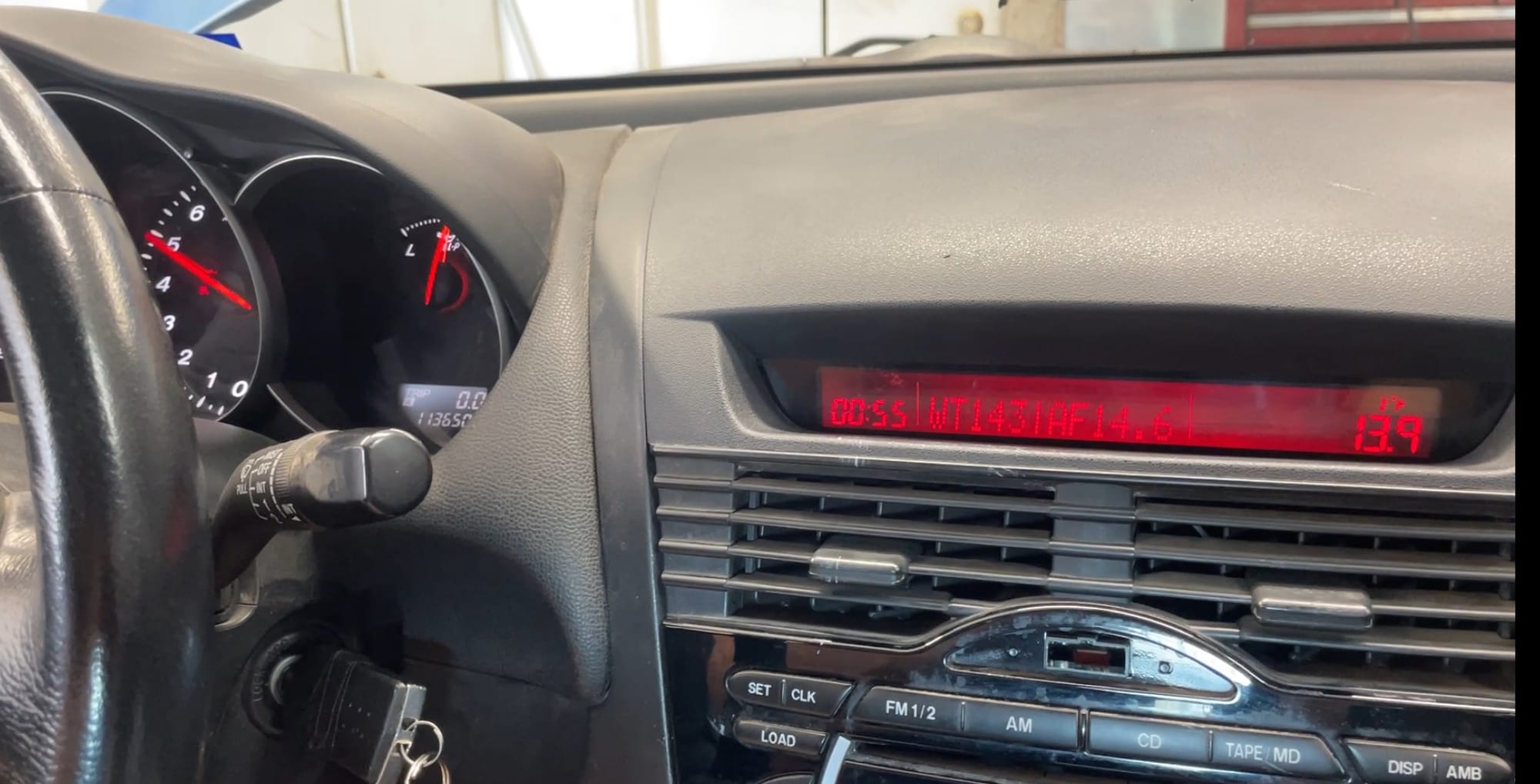
Racing an RX-8 has its challenges - and keeping track of engine status should be the top priority for any owner. The factory 'dummy gauges' are close to useless, cell phones and BT dongles are cumbersome, and well made gauges are expensive. This is my attempt to solve that problem in a fun way.
The goal is to populate the factory LCD screen above the radio with sensor data from the CAN bus and beyond. About 15 years ago, there was a product called the 'Goodbox' that did just this. There are a few problems: it doesn't work without a factory radio installed, and the product hasn't been sold for years. I'm aiming to make my own device that does this. Rather than spend $250 on an off the shelf solution from rotarytronics, I'm going to spend countless hours on a clunky solution - because I want to :)
When it comes to electronics, I'm a noob. I understand the basic principles of electrical engineering like Kirchoff's Laws, but it's rare I do any beyond building wire harnesses or repinning things. This should be a good learning experience
Milestone 1: Controlling The LCD
The Goodbox's original forum post immediately sent me down a few rabbit holes. Someone was kind enough to detail the connector pinout and disassembly of the unit lead me to find the chipset inside. This baby runs off a NJU6623 - and luckily the TDS is readily available! I struggled for a few hours with this until I stumbled upon a gem buried within the UK RX8 forums. A wonderful guy in the UK, Tony Chatfield developed Arduino software to regain factory AC controls without a radio (and display through the LCD!) This is no small task. He reverse engineered the display, all of the encoder inputs, toggle switches, AC data, and shared it for anyone to use.
Not all heroes wear capes
https://github.com/TonyChatfield/S1-RX8-AC-Display-controller
Milestone 2: OBD Data
With a screen to output to, I shifted my focus toward collecting data. It turns out that not all OBD-II cars run on Canbus. Vehicles produced after 2008 will, and I got lucky that the RX8 was ahead of its time. Phew!
I purchased an MCP2515 module with a TJA 1050 can transceiver built in for literally just $3. This little chipset lets you tap into a standard CAN bus and talks to Arduinos via SPI protocol. This just so happens to be the same protocol that our RX8 display uses. More on that later. If you get one of these same boards, you probably want to use the MCP_CAN Arduino library. It's well developed for these specific boards. You'll also need to pay close attention to the fact that most of the ones for sale online have an 8MHz crystal rather than the standard 16MHz, and they include 120ohm resistors but you must stick a jumper on two pins for it to be enabled. It's almost a plug and play solution.
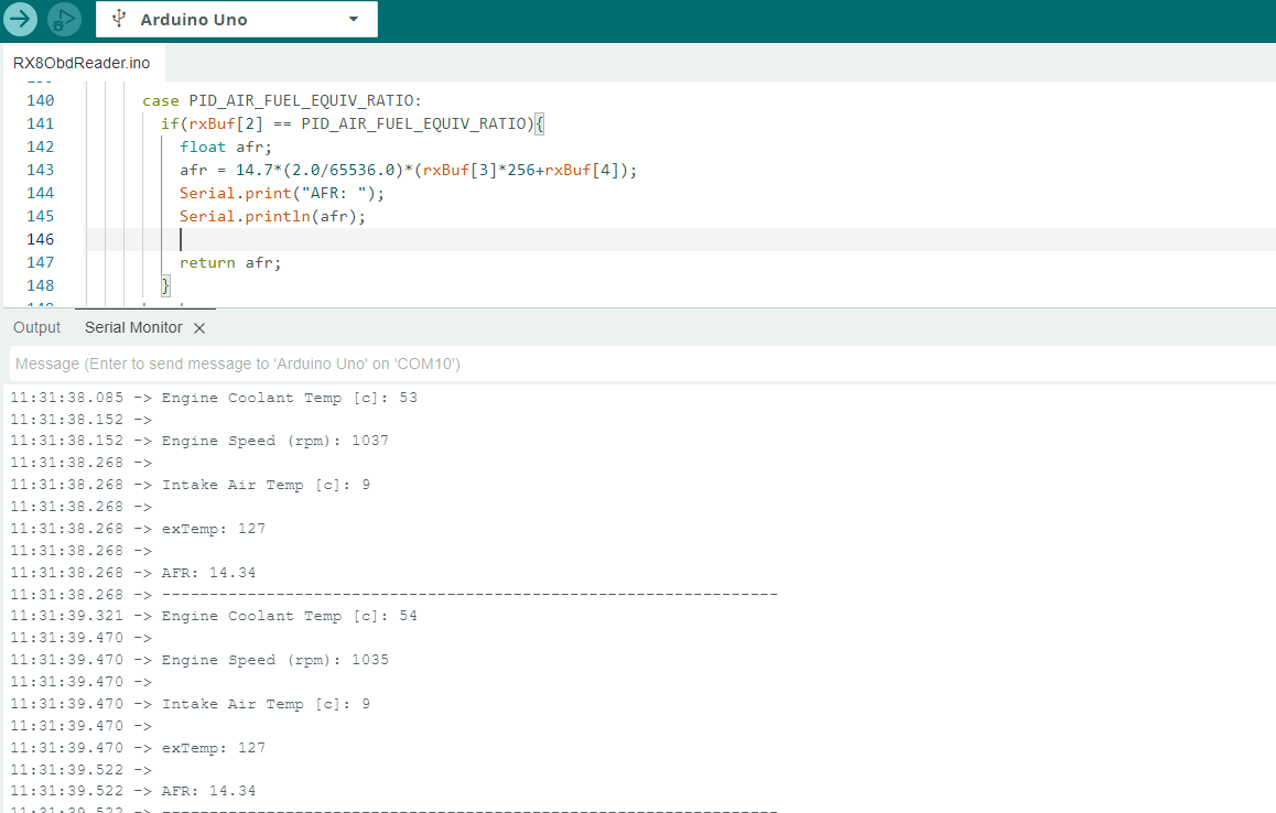
Actually making contact and receiving data is not as trivial as one might think. Every transmission contains a CAN address followed by hexadecimal data. You typically request a specific parameter and wait for the response from the ECU's address. Convert that data to decimal and you're off to the races. It's relatively simple but can be tricky to work with. The good news is that these requests are standardized for common things like engine rpm, coolant temperature, etc. It's documented well here: https://en.wikipedia.org/wiki/OBD-II_PIDs
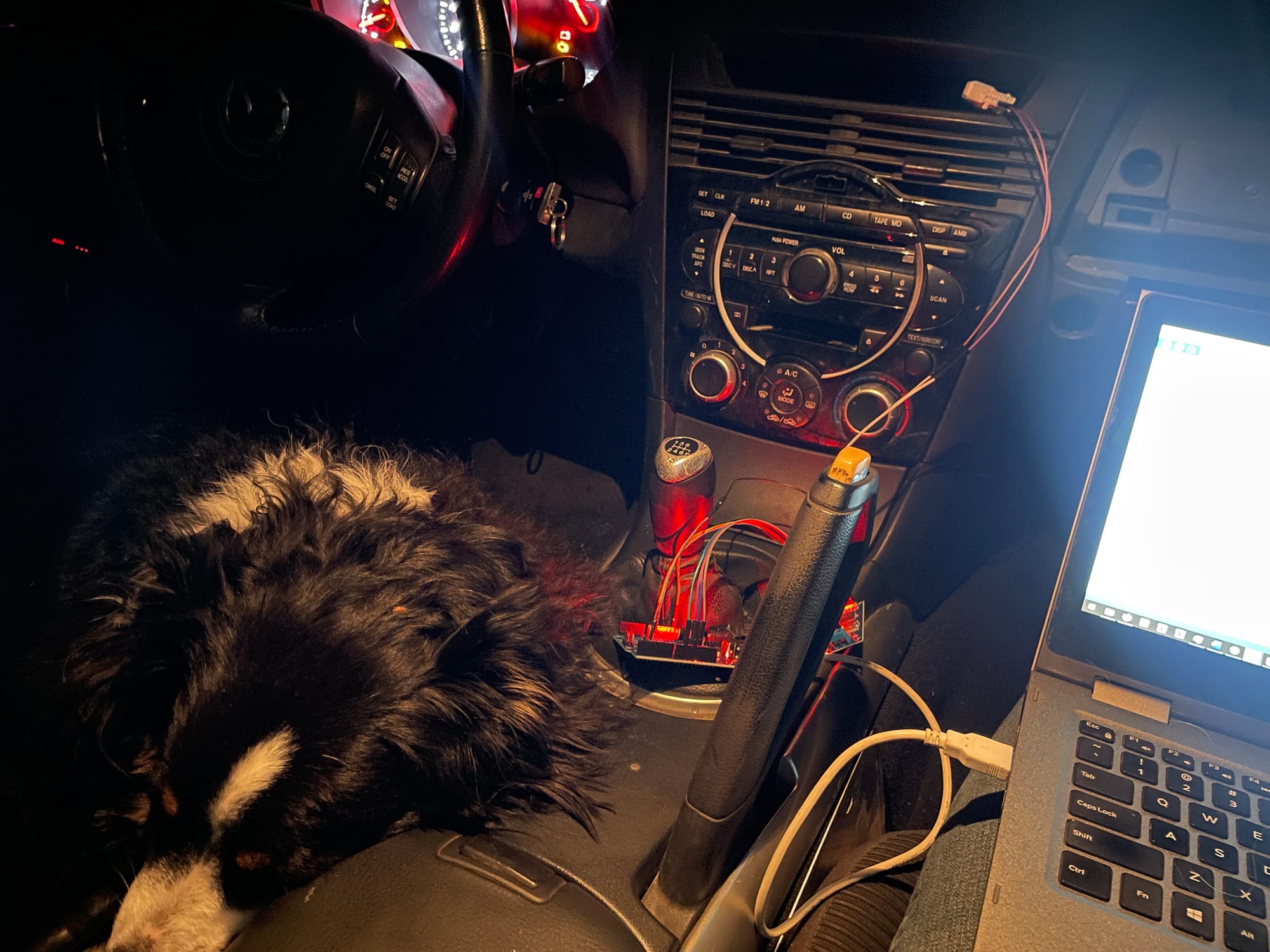
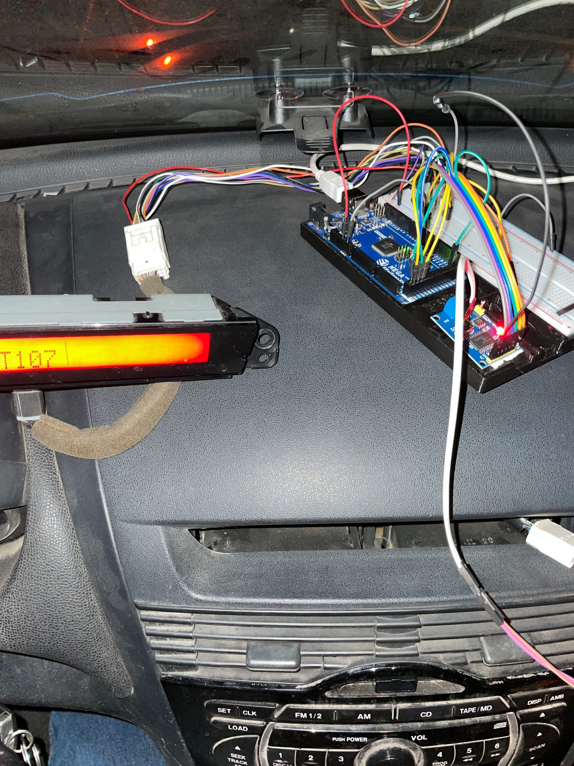
After a few nights of tinkering I managed to get data back from the ECU. The only software task left for was integrating the display and OBD data apps together. Remember how I said these devices both operate with SPI protocol? The Arduino only has one set of dedicated SPI inputs... well sort of - you can actually hard code spi protocol into any digital pins but it's computationally intensive and not necessary here. I learned quickly that you can connect multiple devices to the same SPI lines so long as you have an independent CS (chip select) wire going to each device. With a CS line, the devices know when it's their turn to talk and conflicts are avoided. All it takes is a digitalWrite(LOW) command to select a device and HIGH command when you're done. Some coding and breadboard work later, I was able to output OBD data straight to the display!
The thing works! Well, it works on a breadboard at least. I still needed to package it all and tweak the code more, but the sucker works.
Milestone 3: Final Wiring and Packaging
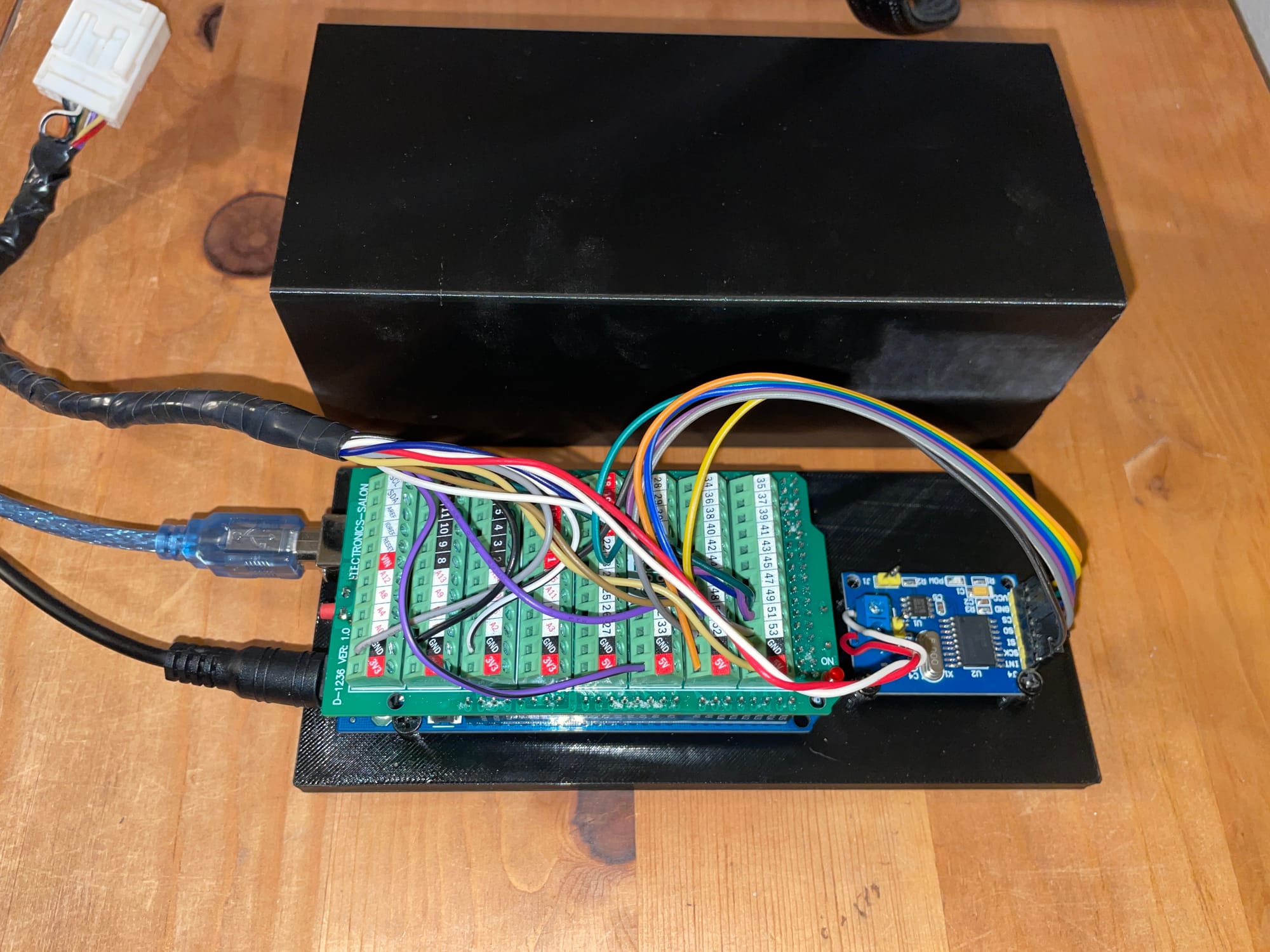
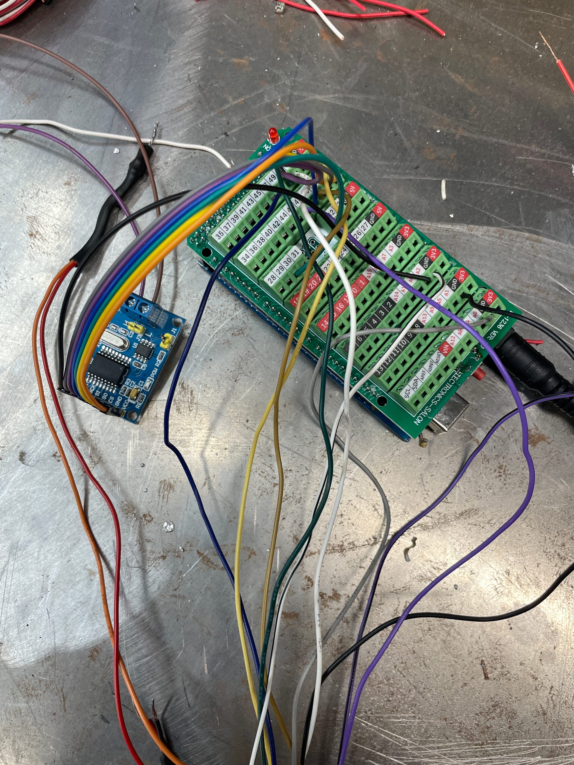
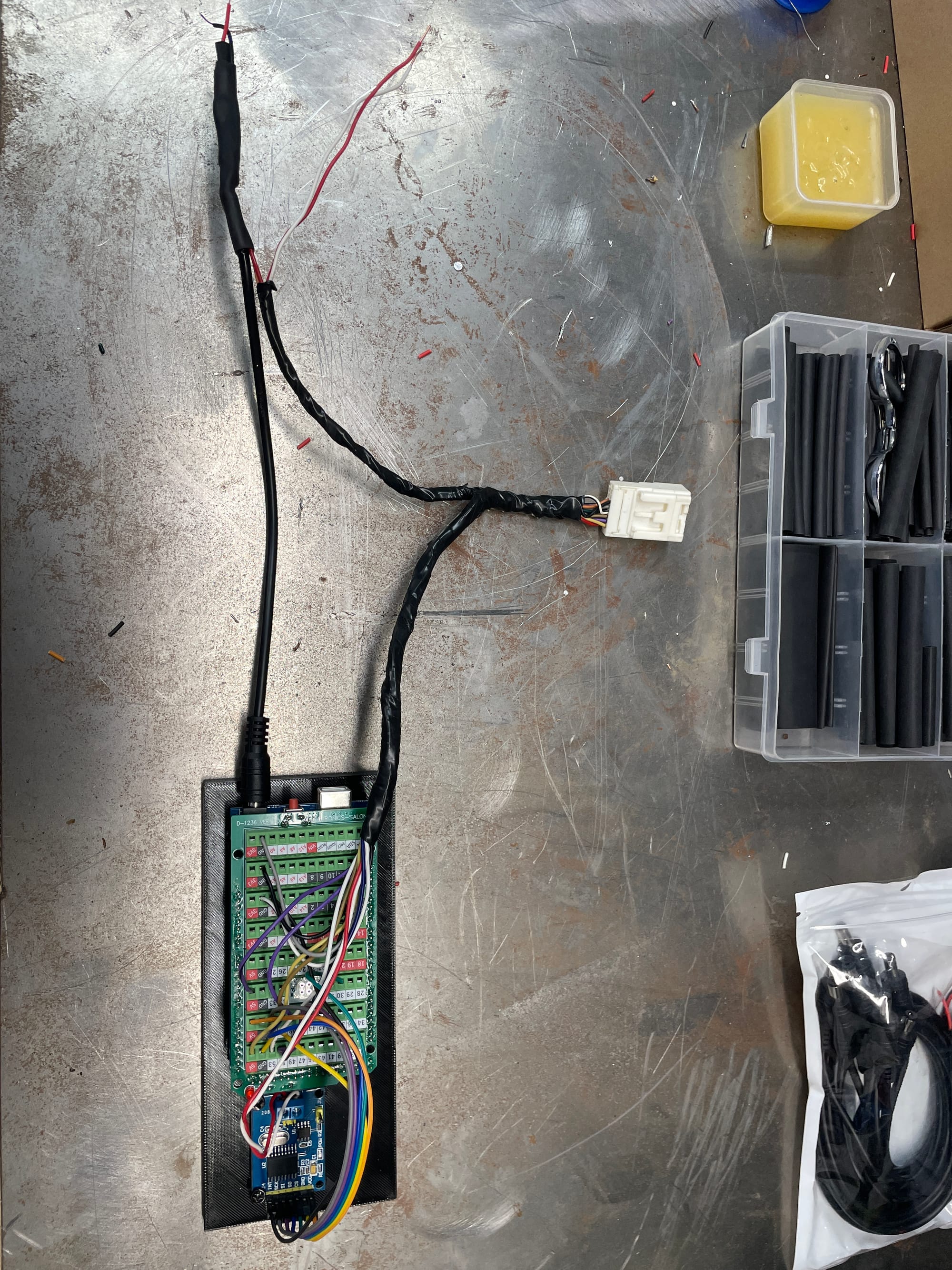
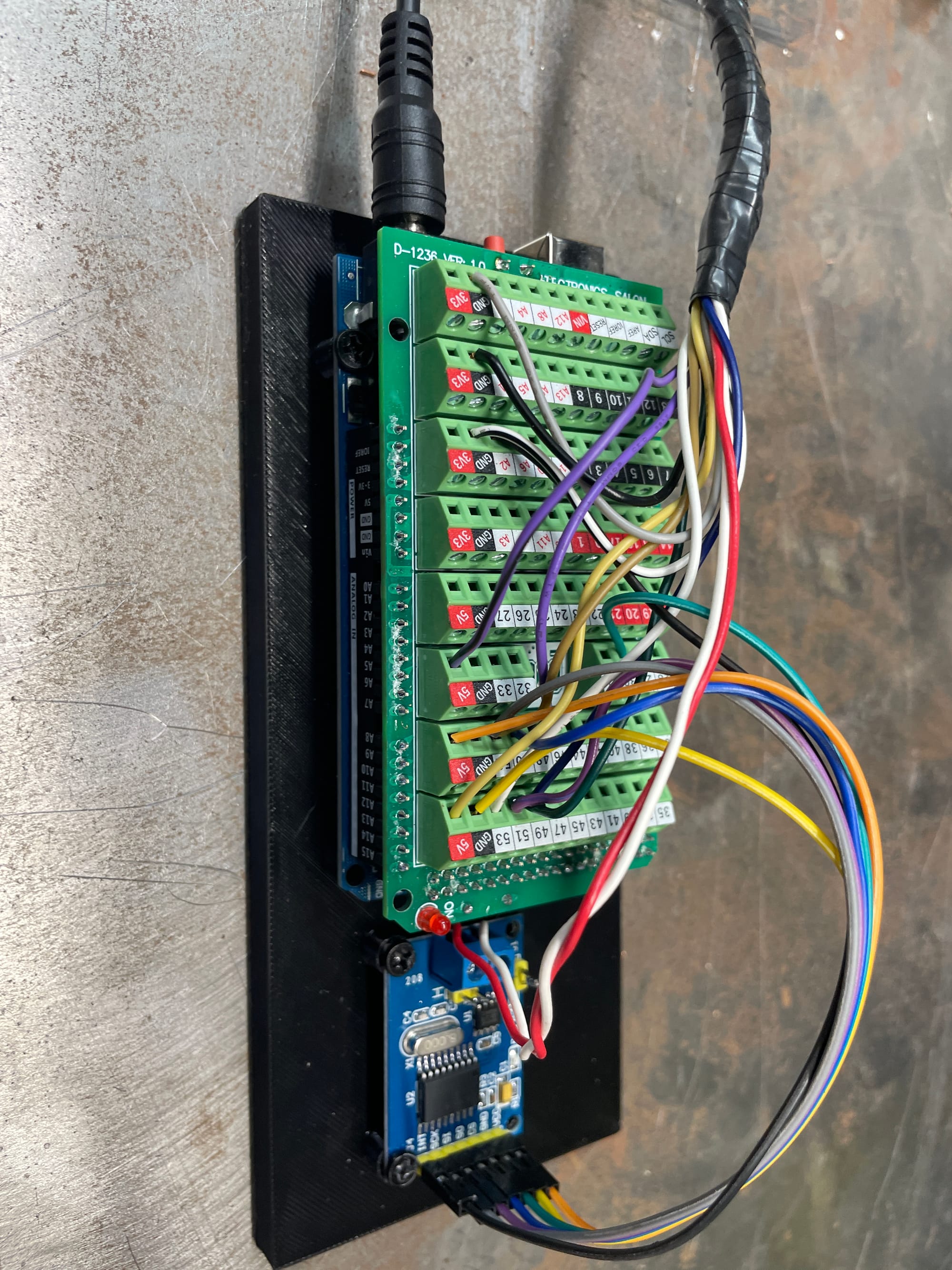
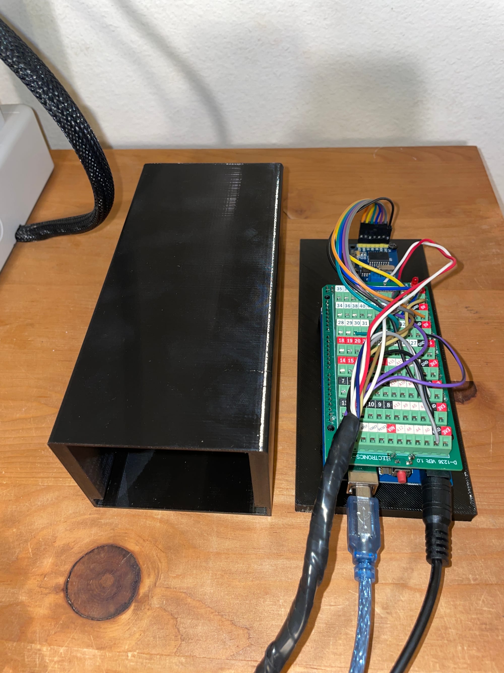
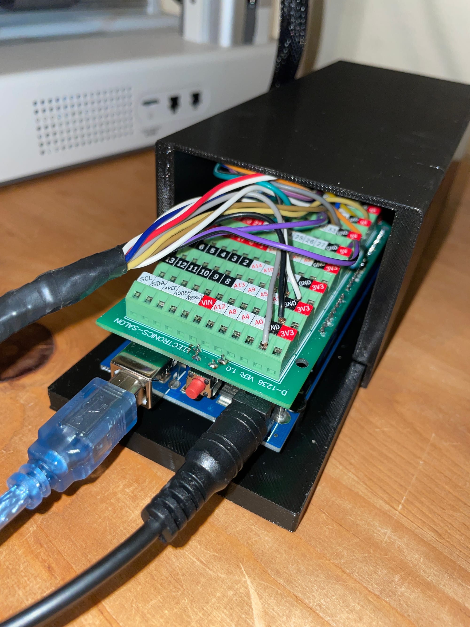
Many companies sell expansion attachments for arduinos - including screw terminal top hats or 'shields' for $30 and up. It felt wrong to spend more on terminals than the microcontroller itself, but I finally gave in. In hindsight, I can't imagine doing this project without one. Wow. If you're considering the same thing, stop wasting time and just get it. Without a radio, I just chopped the display's connector wires off and plugged them into the arduino. Easy. It would have taken hours to painstakingly solder to the arduino.
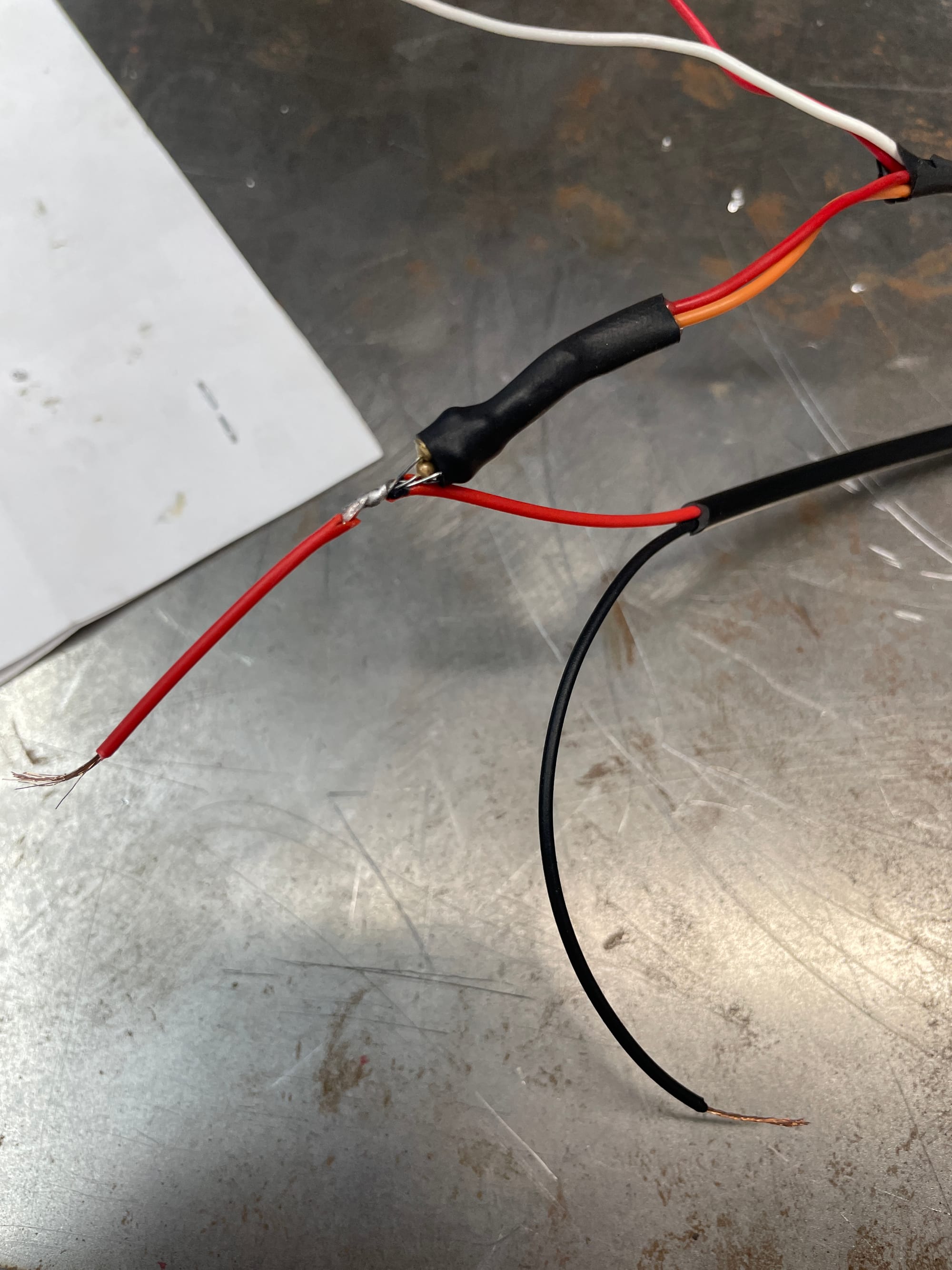
As for external connections, I tied everything into the TPMS module. It's nearby, and all we need is +12v, ground, CAN Hi, CAN Low.
The Arduino can allegedly run off a 12v source for low consumption applications. The CAN transceiver is powered via the Arduino's onboard 5v source, and I used resistors to step down the 12v voltage to about 8V for the LCD driver/backlight. I must admit, using resistors here is probably a lazy approach. For one, I had to use multiple in parallel to prevent them from being overpowered and burning up. Not only that, the resistors were chosen to hit 8V when the engine is running and charging to 14V, otherwise the screen is a bit dim. I'll know with time if I need to upgrade.
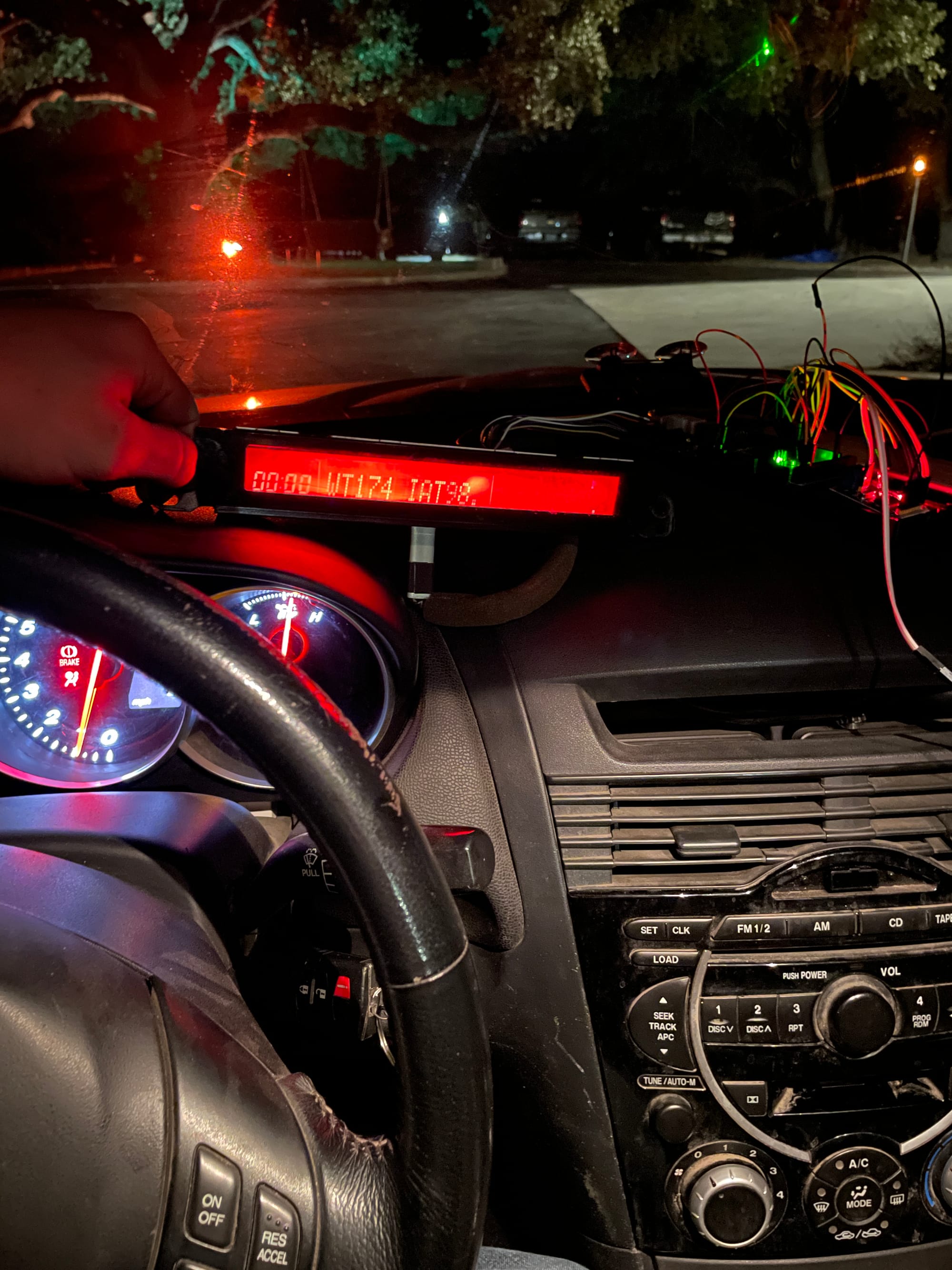
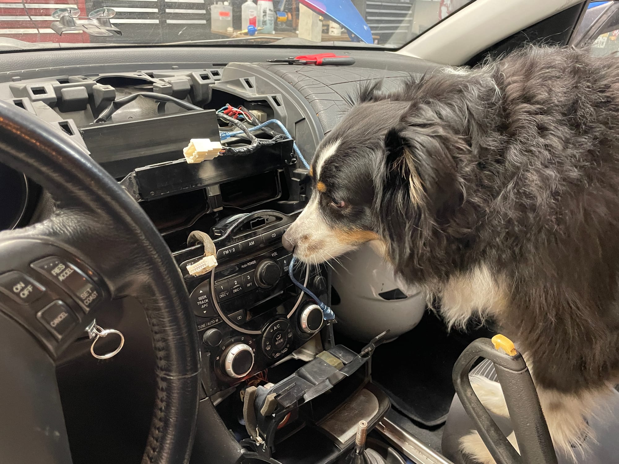
With that done, I 3D printed a basic enclosure and slapped it in the car. Currently it always displays engine coolant temperature and voltage while a secondary area cycles through Air Fuel Ratio, Intake Temps, and Exhaust Temp.
Most importantly, it has passed the pup inspection.
Updates: More Sensors
After living with this for a few months, I decided to add an oil pressure and temperature gauge. Oil gets hot on these, so it's a good idea to keep an eye on temps. Since there's no factory sensors, I purchased an oil filter sandwich plate and used that for my new sensor taps. From there, it was as simple as installing an analog coolant temperature sensor and oil pressure transducer. These got wired into the existing arduino circuit and with a few more lines of code, I have real time oil information.
I'm limited by the small LCD screen, but that's ok with me for now. If you're doing 20 hot laps on a road course, you may want big gauges but I'm not. I've had fun with the project and learned a lot. Plus it makes the car my own.
